UNIGRAPHIX-NX
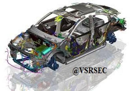
Siemens NX, often referred to as NX or Unigraphics NX, is a high-end, integrated software suite developed by Siemens Digital Industries Software for CAD (Computer-Aided Design), CAM (Computer-Aided Manufacturing), and CAE (Computer-Aided Engineering). It is widely used in industries like automotive, aerospace, manufacturing, and engineering design.
CAD (Design)
- 3D Modeling – Solid and surface modeling tools for creating complex mechanical components.
- Drafting – 2D drawing generation with associative dimensions and annotations.
- Synchronous Modeling – Allows for fast, intuitive editing of models regardless of their history.
- Assemblies – Advanced tools to manage large and complex assemblies with relationships and constraints.
- CAM (Manufacturing)
- Toolpath Generation – Supports milling, turning, drilling, and multi-axis machining.
- Post-processing – Generates G-code for CNC machines.
- Simulation – Visualize and validate machining operations before actual execution.
- CAE (Engineering Analysis)
- Structural Analysis – Finite Element Analysis (FEA) for stress, strain, and deformation.
- Thermal Analysis – Evaluate temperature effects.
- Motion Simulation – Study kinematics and dynamics of assemblies.
Course Outcome
CO1: Understand the User Interface and Workflow
- Identify and navigate the Siemens NX interface and its key modules (CAD, CAM, CAE).
- Demonstrate an understanding of basic terminology and workflow in product design and development.
CO2: Create 2D Sketches and 3D Models
- Create fully defined 2D sketches using appropriate constraints and dimensions.
- Develop 3D models using features like extrude, revolve, sweep, loft, and more.
CO3: Perform Assembly Modeling
- Create and manage multi-component assemblies.
- Apply constraints and relationships between components for proper fit and function.
CO4: Apply Advanced Modeling Techniques
- Use surface modeling and synchronous modeling for complex geometry.
- Modify and optimize models using parametric and direct editing tools.
CO5: Generate Engineering Drawings
- Create 2D drawings from 3D models with proper views, annotations, and dimensions.
- Apply industry-standard drawing practices and tolerances.
CO6: Understand CAM Functionality (Optional or Advanced Level)
- Generate tool paths for CNC machining.
- Simulate and verify machining operations.
CO7: Apply Basic Simulation (Optional or Advanced Level)
- Perform basic finite element analysis (FEA) for stress, thermal, or motion studies.
- Interpret simulation results to make design decisions.
CO8: Integrate with Product Lifecycle Management (PLM)
- Understand the role of PLM and integration with tools like Teamcenter (if applicable).
- Manage revisions and track design changes.


Review Course
For Review on Course. You need to Login first. Login Here